Topographic Line Art with WebGL
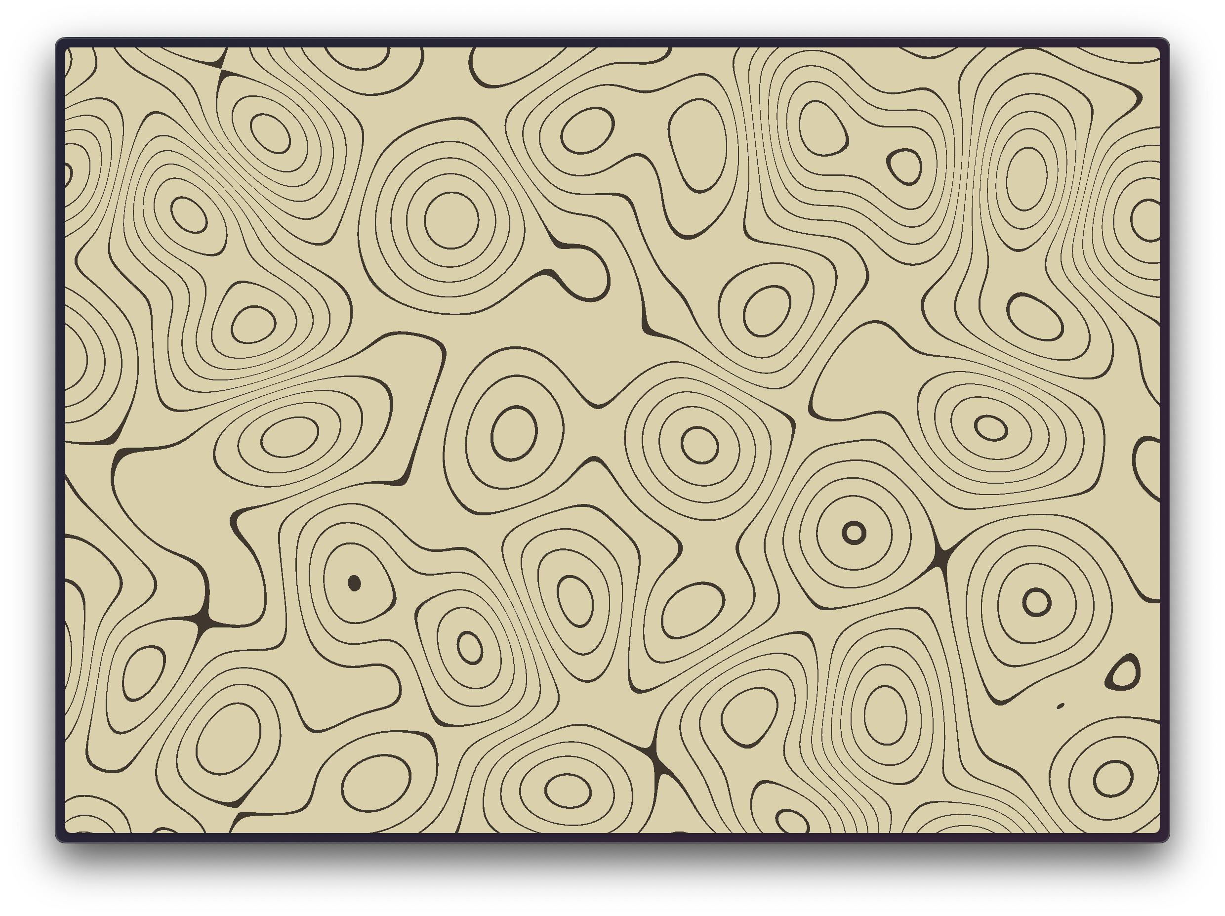
Back in early-mid 2021, I saw this art style everywhere, especially in brandings. So much so that I actually own a desk mat that looks exactly like it. This is what I’m talking about:
The full code for it is here, for the impatient: TL;DR
Basic Setup
The first thing I did was research; how were designers making this? It seemed too complex to build out by hand, and yet too organized to be random. It had to be procedurally generated, right? I found this tutorial, among others. The general idea seemed to be to start with some Perlin noise, blur it, adjust levels to increase contrast, and then detect edges. We’re not quite doing that, but we’ll go a similar route.
We’ll use three.js to build this. There are many ways to set up a basic playground, but I’ll stick to the basics. I’ll spin up a quick Vite project to get hot reloading support, but you can literally just have an HTML page:
<html>
  <div id="topo"></div>
  <script type="module" src="./src/index.ts"></script>
</html>
In our JavaScript file, we’ll set up a basic ThreeJS scene. If you’re new to this
stuff, three’s docs
have a basic tutorial to get you started. That being said, I’d really recommend
getting comfortable with graphics terminology before progressing, since most things
will just sound like gibberish otherwise. I’ll mostly rush over the ThreeJS-specific
things so we can get to the interesting bits. Because we’ll do all our coding in
a shader, what I want from Three is just a simple scene with a plane that covers
our camera’s view entirely. I’ll set up an OrthographicCamera
and my plane this way:
const width = 600;
const height = 400;

const scene = new THREE.Scene();

// Create and position the camera so its FOV maps exactly to our viewport
const camera = new THREE.OrthographicCamera(0, width, 0, height, 1, 3);
camera.position.z = 2;

const renderer = new THREE.WebGLRenderer();
renderer.setSize(width, height);

// Just a plane will do
const geometry = new THREE.PlaneGeometry(width, height);
geometry.translate(width / 2, height / 2, 0);

// We'll start off with a white-colored material
const material = new THREE.MeshBasicMaterial({
  color: 0xffffff,
  side: THREE.DoubleSide, // Make sure both sides of the Plane are rendered. This avoids normal-related issues.
});
scene.add(new THREE.Mesh(geometry, material));

document.getElementById("topo").appendChild(renderer.domElement);
function frame() {
  requestAnimationFrame(frame);
  renderer.render(scene, camera);
}
frame();
If all goes well, you should see a white canvas. Nice.
Let’s swap the MeshBasicMaterial
with a ShaderMaterial
and write a basic vertex and fragment shader so we can make sure they work as well:
// ..snip

const vs = `
  void main() {
    gl_Position = projectionMatrix * modelViewMatrix * vec4(position, 1.0);
  }
`;
const fs = `
  void main() {
    gl_FragColor = vec4(1.0, 0.0, 0.0, 1.0)
  }
`;
const material = new THREE.MeshBasicMaterial({
  vertexShader: vs,
  fragmentShader: fs,
  side: THREE.DoubleSide,
});

// ..snip
(Okay listen, there are better ways to handle shaders than shoving them in a string, but everyone has their own way to handle them, so do what you prefer. In this post, I’ll just keep them in a string to keep things simple.)
Your white canvas should now turn red. With all this done, let’s get to the fun
stuff.
Shaders
Let’s create some Perlin noise. We could do this on the JS side of things (on the
CPU), but since I plan on animating the noise, doing this would get expensive
real quick since we’d have to do it at least 60 times a second. Instead, we’ll do this
on the GPU, which is extremely good at this kind of thing. Writing a Perlin noise
function in GLSL is way beyond this post, so I found one.
that I’ll just copy into my fragment shader, above the main function. Then we
can use the snoise function’s return value to generate the fragment color:
// Paste the contents of `noise3D.glsl` here
void main() {
float noise = snoise(vec3(gl_FragCoord.xy, 1.0));
gl_FragColor = vec4(vec3(noise), 1.0);
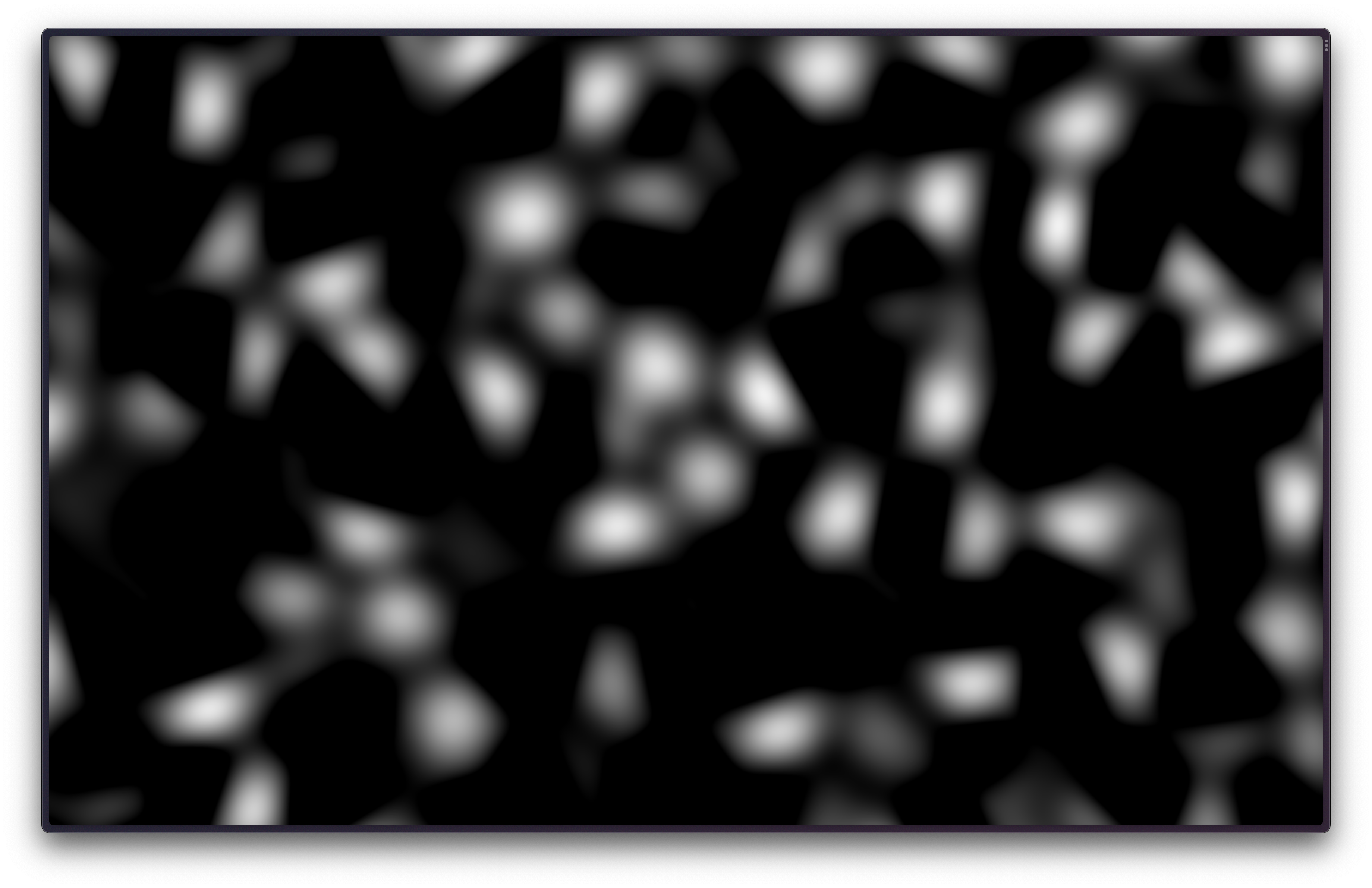
}You won’t see much yet, because the noise is far too small. Let’s multiply gl_FragCoord.xy
by 0.005 to “zoom in” a little:
You might notice that there’s more black than white though, and that’s because the
snoise function returns values between -1 & 1. Fragment shader output is clipped
to be between 0 & 1, so we’ll need to “normalize” it. Normalizing in the context of
shaders is just fancy talk for scaling a value from whatever range it is in to [0-1]
void main() {
  float noise = snoise(vec3(gl_FragCoord.xy * 0.005, 1.0)); // Get noise
  noise = (noise + 1.0) / 2.0; // Normalize it
  gl_FragColor = vec4(vec3(noise), 1.0);
}
Next up, we want to change the noise so that it isn’t smooth like it is right now.
What we want are “bands” of colors. This is exactly what posterization
is. This
is a great resource for learning about posterization (and tons of other stuff).
In a nutshell, we’re trying to convert a continuous range of values between 0 & 1
(aka our noise) into discrete steps. Think of it as rounding values up/down, so
everything between 0 & 1 gets converted to 1, everything between 1 & 2
gets converted to 2, and so on.
It isn’t exactly like rounding though, because our noise value is already between
0 & 1. So let’s multiply our noise value by 10 to scale it to [0-10], then
do our “rounding” operation:
void main() {
  float noise = snoise(vec3(gl_FragCoord.xy * 0.005, 0.0));
  noise = 10.0 * (noise + 1.0) / 2.0;

  float rounded = ceil(noise);
  float color = rounded / 10.0; // We must scale the rounded value back to [0-1] so we can use it as a valid color
  gl_FragColor = vec4(color, color, color, 1.0);
}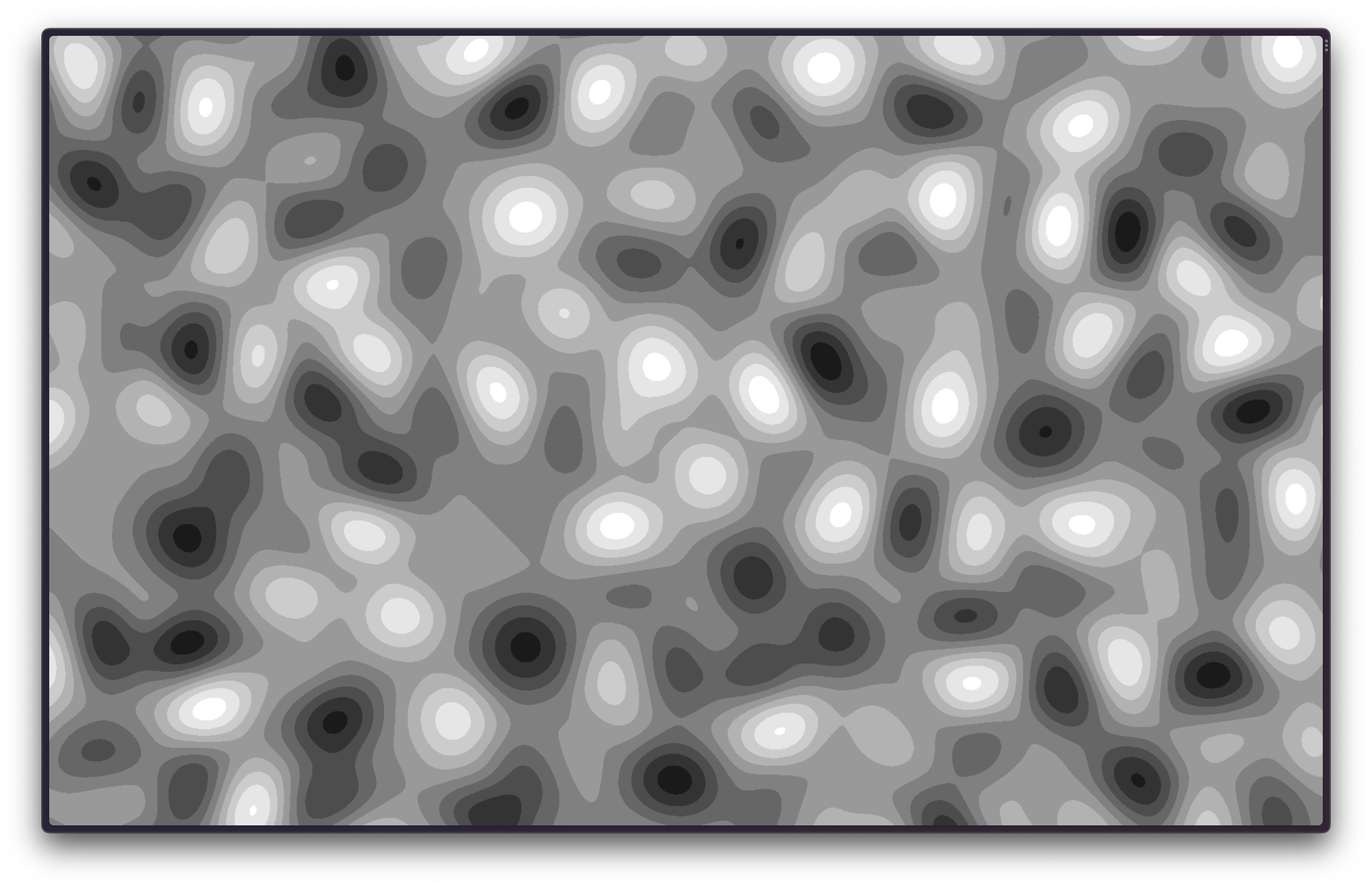
Hey, now we’re getting somewhere! What we want though aren’t bands of colors, we want
the edges of these bands of colors. Instead of implementing a fancy edge detection
algorithm, we can use the fact that during posterization, we just rounded down the
actual value of the Perlin noise. If you think about it, places where the actual
value and the rounded value differ by less than 0.1 (or any small threshold)
are (roughly) the “edges”! We’ll draw a white pixel in these places, and a black
pixel otherwise. Let’s try that out:
void main() {
  float noise = snoise(vec3(gl_FragCoord.xy * 0.005, 0.0));
  noise = (noise + 1.0) / 2.0; // normalize it

  float rounded = ceil(noise);
  float rounding_error = rounded - noise;

  if (rounding_error < 0.1) {
    gl_FragColor = vec4(1.0, 1.0, 1.0, 1.0);
  } else {
    gl_FragColor = vec4(0.0, 0.0, 0.0, 1.0);
  }
}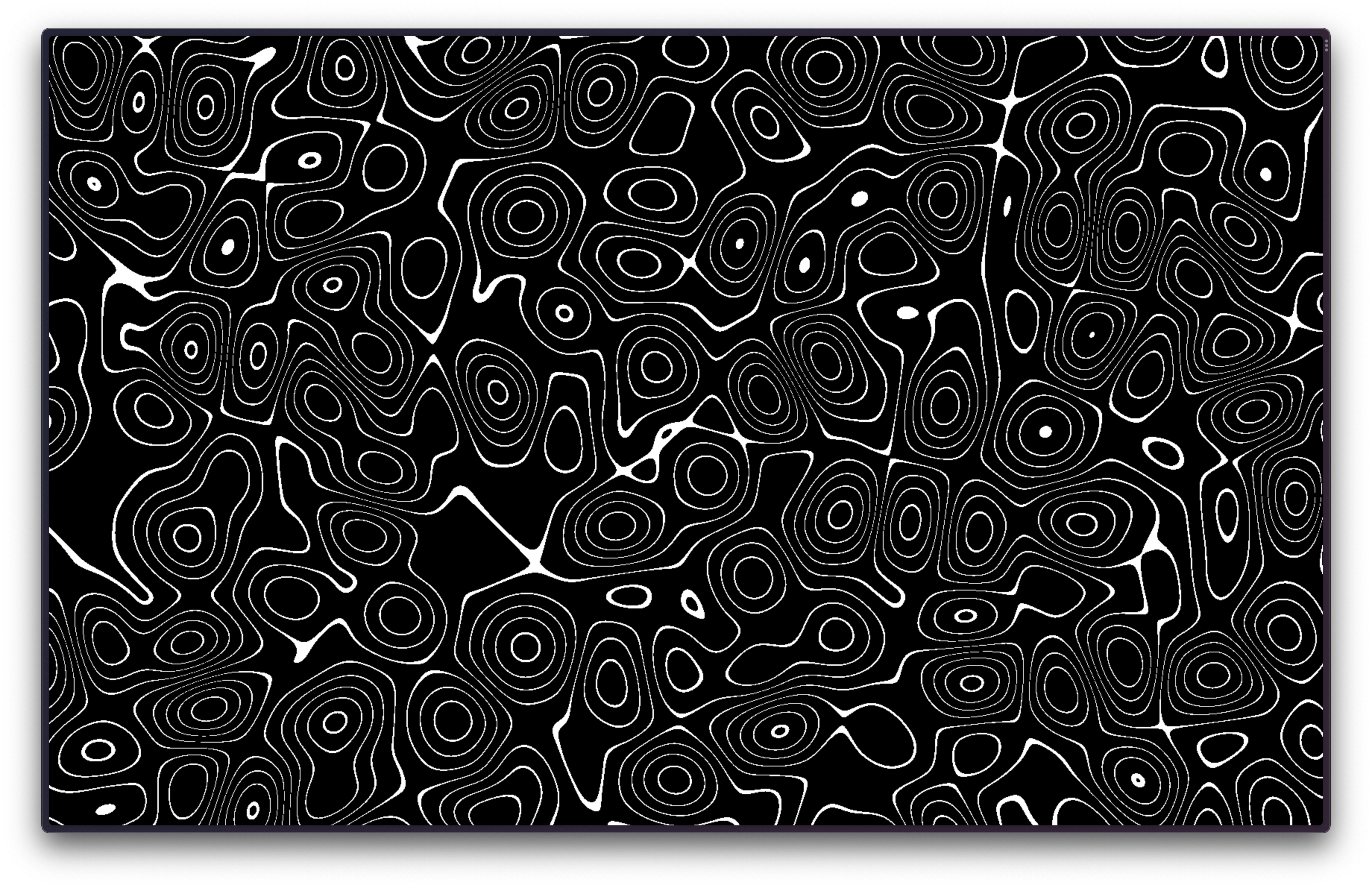
There we go! We could end here, but there are a few obvious improvements we can make here. The most obvious one is to improve the jagged lines. That’s as simple as telling ThreeJS to use our device’s pixel ratio. We can do that by adding this to our ThreeJS code:
renderer.setPixelRatio(window.devicePixelRatio);This makes everything much smaller, so we can bump the size up again by “zooming in”
more, aka changing the coefficient we multiply the gl_FragCoord.xy by. I’ll set
it to 0.003, but you should use a value that looks good to you!
Second, instead of painting a fragment black, we can just discard it, or tell WebGL
to not paint it at all. This also has the advantage that our final material becomes
transparent, which means it will blend with our page’s background better. Make sure
you set the alpha parameter in your WebGLRenderer constructor call as well!
void main() {
  float noise = snoise(vec3(gl_FragCoord.xy * 0.003, 1.0));
  noise = 10.0 * (noise + 1.0) / 2.0;

  float rounded = ceil(noise);
  float rounding_error = rounded - noise;

  if (rounding_error > 0.1)
    discard;

  gl_FragColor = vec4(1.0, 1.0, 1.0, 1.0);
}
Animation
You might have noticed that there’s a second parameter to the snoise function
that we’ve set to 1 so far. This value is actually supposed to be a “time” value,
and is part of the Perlin noise algorithm. If you set it to something other than 1.0,
you’ll see a different pattern from your shader. What’s incredibly cool though is
similar values of this time value produce “similar” Perlin noise patterns. What
I mean is that a time value of 1.1 creates a pattern that is only slightly
different from the one we’ve been seeing. Think of it as a “phase” parameter instead
of “time”. We can use this to our advantage by setting it to the value of ThreeJS’s
clock. Because it increases continuously, we should also see our Perlin noise
pattern slowly change over time. Let’s create a Clock
and use it as a uniform in our ShaderMaterial:
// ..snip
const clock = new THREE.Clock();
// ..snip
const material = new THREE.ShaderMaterial({
  uniforms: {
    time: {
      value: clock.startTime,
    },
  },
  vertexShader: vs,
  fragmentShader: snoise + fs,
  side: THREE.BackSide,
});
and of course we’ll have to tell our fragment shader about this uniform as well,
so we can pass it into the snoise function:
uniform float time;

void main() {
  float noise = snoise(vec3(gl_FragCoord.xy * 0.003, time));
  noise = 10.0 * (noise + 1.0) / 2.0;

  float rounded = ceil(noise);
  float rounding_error = rounded - noise;

  if (rounding_error > 0.1)
    discard;

  gl_FragColor = vec4(1.0, 1.0, 1.0, 1.0);
}
You might notice that your pattern changed drastically, but there’s no animation 🤔
Well that’s because we set the uniform once, but we never update it! We’ll have
to make sure we update our time uniform in our render loop:
// ..snip
function frame() {
  requestAnimationFrame(frame);

  material.uniforms.time.value = clock.startTime + clock.getElapsedTime();
  renderer.render(scene, camera);
}
frame();
Whoa! You should see a trippy-looking animation! Of course it’s too quick, so we
can slow it down by just multiplying the time uniform we pass to the snoise
function by a small number, such as 0.01
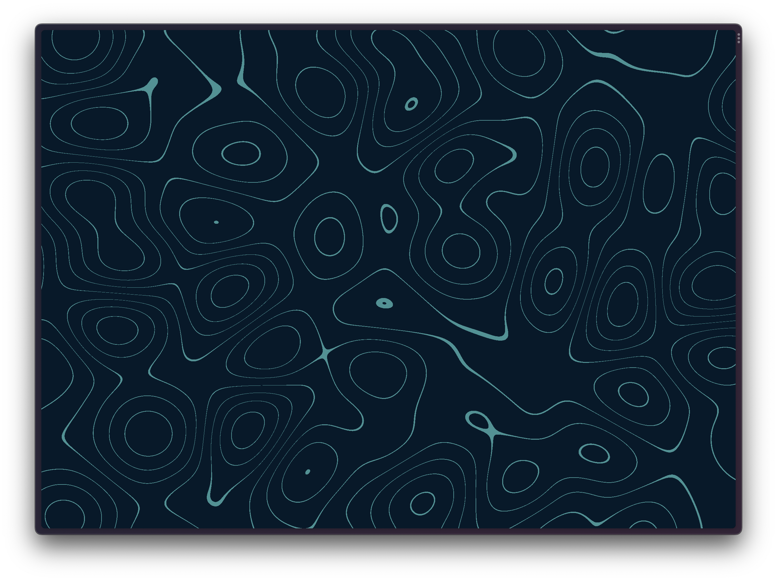
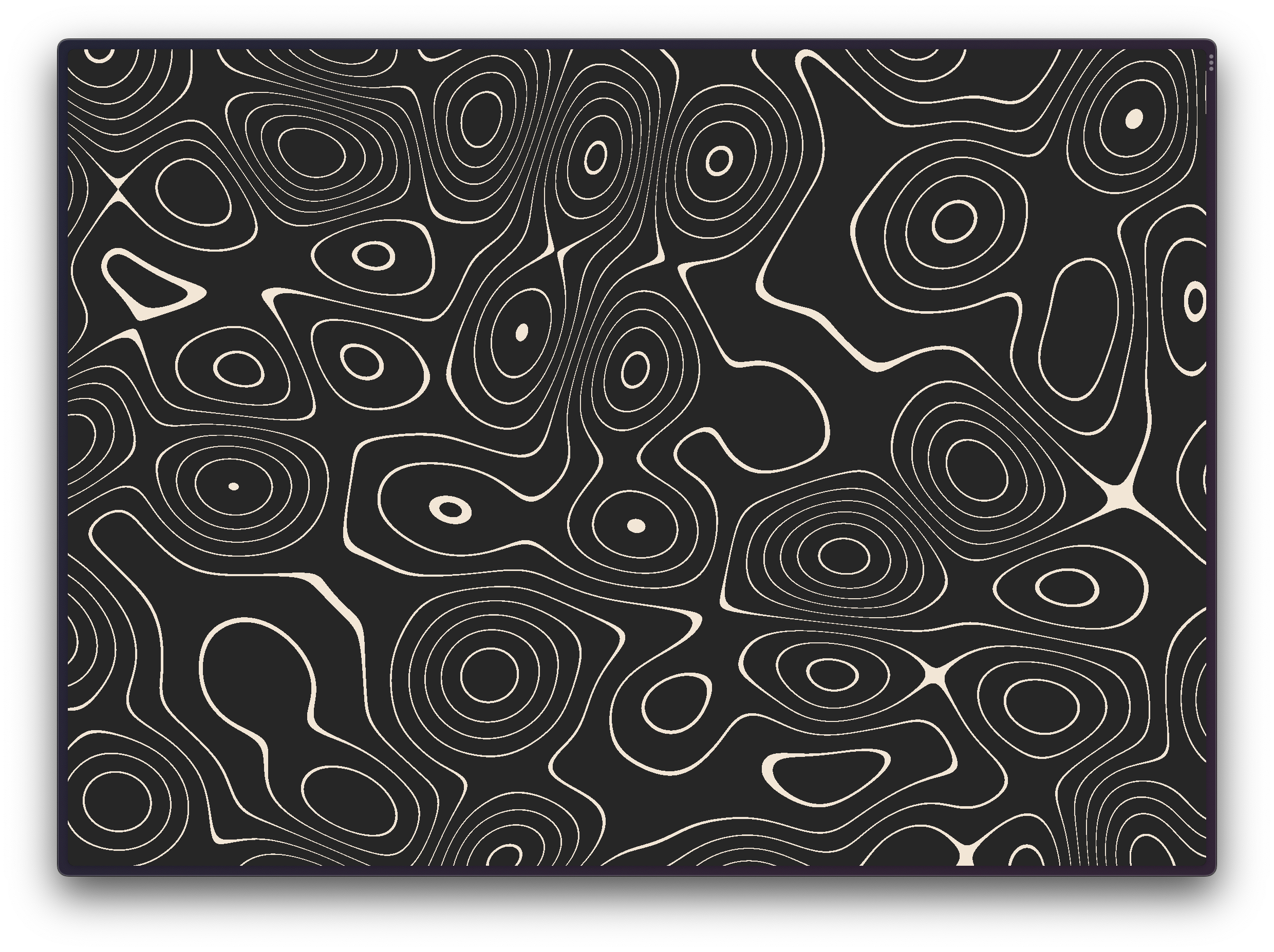
That’s all there is to it! One more thing you can do is create a color uniform
so you can control what color you paint in the fragment shader, but I’ll leave that
to you. Here are a few color combinations that I think work well, to end things off:
TL;DR
The final shader I use is a little more complex, but only because it has a couple of knobs to give me a bit more control over the look of the pattern. You’ll find it on my GitHub